GRIDBASE Modular Platform System
DESIGN PRINCIPLES
The GRIDBASE Modular Platform System is designed around a standardised 2000mm × 2000mm elevated modular platform panel. This system has been developed based on five core design principles:
Reusable: Panels can be removed, relocated, and redeployed without permanent site modifications.
Low Ground Impact: Installation does not require excavation, concrete footings, or permanent ground disturbance, making it ideal for modular infrastructure.
Modular: The standardised panel design allows systems to be expanded, reconfigured, and adapted to suit changing project requirements.
Multi-Purpose: The platform is suitable for a variety of applications, including residential, modular housing, commercial, mining, and remote infrastructure projects.
Rapid Deployment: Independent levelling and modular connections facilitate rapid deployment, allowing platforms to be installed with minimal site preparation.
Core System Components

The GRIDBASE system consists of six primary components:
1. Structural Steel Frame
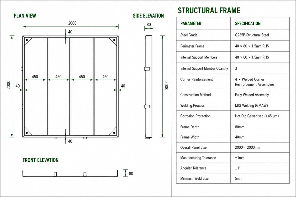
Manufactured from Q235B structural steel, the welded RHS frame forms the primary load-bearing structure of the platform. The frame is hot dip galvanised after fabrication to provide corrosion protection in accordance with AS/NZS requirements.
2. WPC Composite Decking
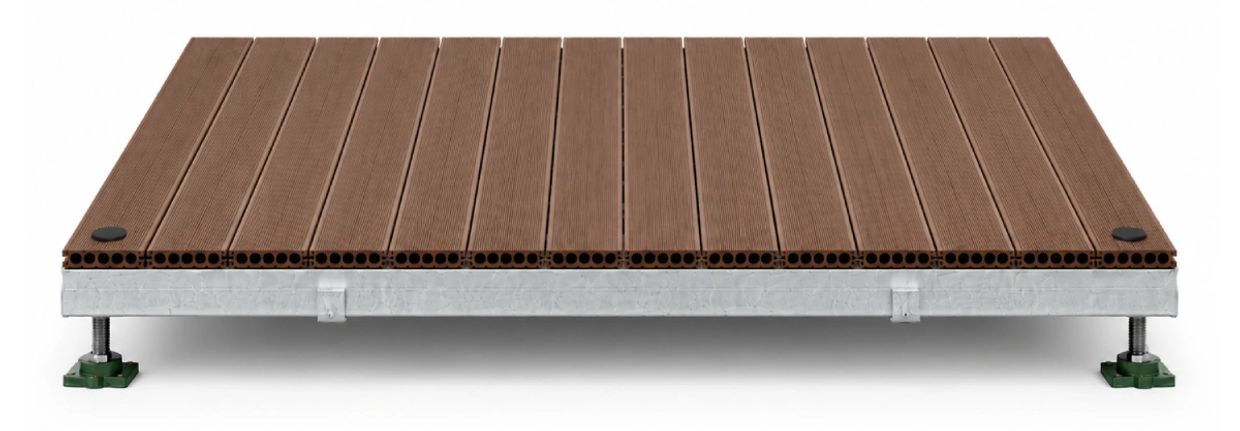
Each panel is fitted with 14 WPC composite decking boards measuring 2000 × 139 × 25mm. The boards provide a durable, low-maintenance walking surface with an anti-slip profile and consistent 4mm board spacing for drainage.
3. Adjustable Levelling Legs
Each corner is supported by an M20 threaded adjustable levelling leg, allowing independent height adjustment to accommodate uneven ground.
4. Integrated Connection System
Each panel incorporates an integrated steel connection system that mechanically joins adjacent panels into a continuous platform. The concealed latch design provides structural alignment while allowing panels to be relocated and reconfigured.
5. Levelling Leg Access Points
Integrated access ports within the decking provide direct access to the levelling mechanism after installation. Legs can be adjusted from above the platform using standard hand tools without removing decking boards or dismantling the platform.
6. Articulating Foot Assembly
The articulating foot incorporates a multi-directional bearing surface allowing full contact with uneven ground. This improves load distribution and stability while maintaining the vertical alignment of the threaded levelling leg.
Structural Steel Frame
STRUCTURAL PERFORMANCE

Deflection Analysis

Under Deflection Analysis
Maximum Deflection: 2.4mm
Finite Element Analysis (FEA) indicates a maximum calculated deflection of 2.4mm under a uniformly distributed load of 400kg/m² applied across the panel surface of the modular platform. This analysis supports the efficiency of modular infrastructure in achieving rapid deployment solutions.
Under Stress Distribution
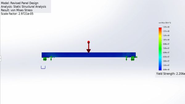
Maximum von Mises Stress: 150MPa
The FEA stress analysis of our modular platform indicates a maximum calculated von Mises stress of approximately 150MPa under the specified loading conditions, showcasing the effectiveness of our modular infrastructure in enabling rapid deployment.